
 Language
 YYW Universal Joint Balancing Machine: High-Precision Universal Shaft Balancing Correction & Universal Joint Drive Dynamic Balancing Machine Operation Flow
YYW Universal Joint Balancing Machine: High-Precision Universal Shaft Balancing Correction & Universal
Joint Drive Dynamic Balancing Machine Operation Flow
In modern industrial manufacturing and machinery maintenance, vibration in rotating equipment is the primary culprit behind premature wear and shortened lifespan.
To effectively solve this critical issue, the YYW Universal Joint Balancing Machine has become the top choice for global enterprises, thanks to its robust driving capacity and exceptional measurement accuracy.
In this comprehensive guide, we will dive deep into the core balancing technology of this equipment and share the standard universal joint drive dynamic balancing machine operation flow.
This will empower you to achieve perfect high-precision universal shaft balancing correction in your daily production.
1. Why Choose the YYW Universal Joint Balancing Machine? Core Technology Analysis
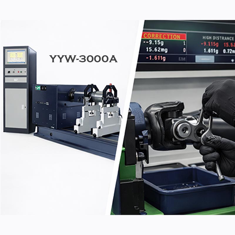
The YYW Universal Joint Balancing Machine is a hard-bearing horizontal dynamic balancing machine that utilizes a universal coupling drive system. Compared to belt-drive machines, the universal joint can transmit significantly higher torque. This makes it highly suitable for an industrial rotating workpiece dynamic balancing test, including fan impellers, large water pump impellers, paper-making rollers, and heavy motor rotors.
Its core technological advantages include:
·Robust Transmission System: The universal coupling drives the rotor directly, ensuring smooth startup and eliminating belt slippage. This guarantees data accuracy in any large motor rotor dynamic balancing solution.
·Advanced Microcomputer System: Modern YYW series are equipped with a state-of-the-art microcomputer measuring system dynamic balancing instrument. It displays rotational speed, unbalance amount, and phase angles in real-time with strong anti-interference capabilities.
·High-Sensitivity Sensors: Featuring piezoelectric sensors with excellent linearity, the machine easily achieves high-precision universal shaft balancing correction, strictly meeting the ISO 1940 balancing accuracy grades.
2. Universal Joint Drive Dynamic Balancing Machine Operation Flow Explained
For operators, mastering the standardized universal joint drive dynamic balancing machine operation flow is the key to ensuring accurate test data and operational safety. Below are the detailed step-by-step instructions:
Step 1: Equipment and Rotor Preparation
Before starting, clean the machine's guide rails and roller carriages. Ensure the journals of the rotor to be tested are clean and free of oil to prevent additional vibrations on the rollers. This preparation is especially crucial when using it as centrifuge rotor balance verification equipment.
Step 2: Workpiece Installation and Joint Connection
Adjust the distance between the left and right support pedestals according to the rotor's shaft distance, then lock them tightly. Place the rotor smoothly onto the rollers. Next, select an appropriately sized transition flange to connect the universal joint coupling firmly to the rotor's end face. Ensure concentricity to avoid initial unbalance interference.
Step 3: System Parameter Input
Boot up the microcomputer control system. Input the geometric parameters of the rotor into the software interface, which typically include:
·A, B, C Values: The distances from the support planes to the correction planes.
·R1, R2 Values: The radii of the left and right correction planes (where weight will be added or removed).
Accurate parameter input is the foundation of a successful water pump impeller double-sided dynamic balancing test.
Step 4: Start Measurement and Read Data
Close the safety guard (if applicable) and press the start button. The machine will drive the rotor to the preset balancing speed. The screen will display the unbalance magnitude (usually in g or g·mm) and the specific phase angles for both the left and right planes.
Step 5: Weight Addition / Removal Correction
Once the machine stops, manually rotate the rotor to the angle indicated by the screen. Depending on your process requirements, perform "weight addition" (e.g., welding counterweights) or "weight removal" (e.g., drilling, grinding) on the corresponding correction planes. For massive rotors, this step is the core of heavy machinery rotating shaft dynamic balancing.
Step 6: Retesting and Reporting
After weight correction, restart the YYW Universal Joint Balancing Machine for a retest. When the unbalance amount displayed on the screen falls within the acceptable tolerance range, the balancing is complete. Finally, you can generate and print a balancing test report with one click for quality assurance archiving.
3. Conclusion and Maintenance Tips
Implementing a scientific universal joint drive dynamic balancing machine operation flow not only drastically improves production efficiency but also extends the equipment's lifespan. We recommend regularly lubricating the roller bearings and calibrating the sensors and microcomputer system annually with standard test rotors. This ensures your machine always delivers reliable high-precision universal shaft balancing correction.

Related products
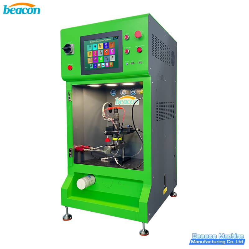
BEACON MACHINE EPS290 Integrated Common Rail Fuel Delivery Analyzer | Professional Diesel Injector Tester
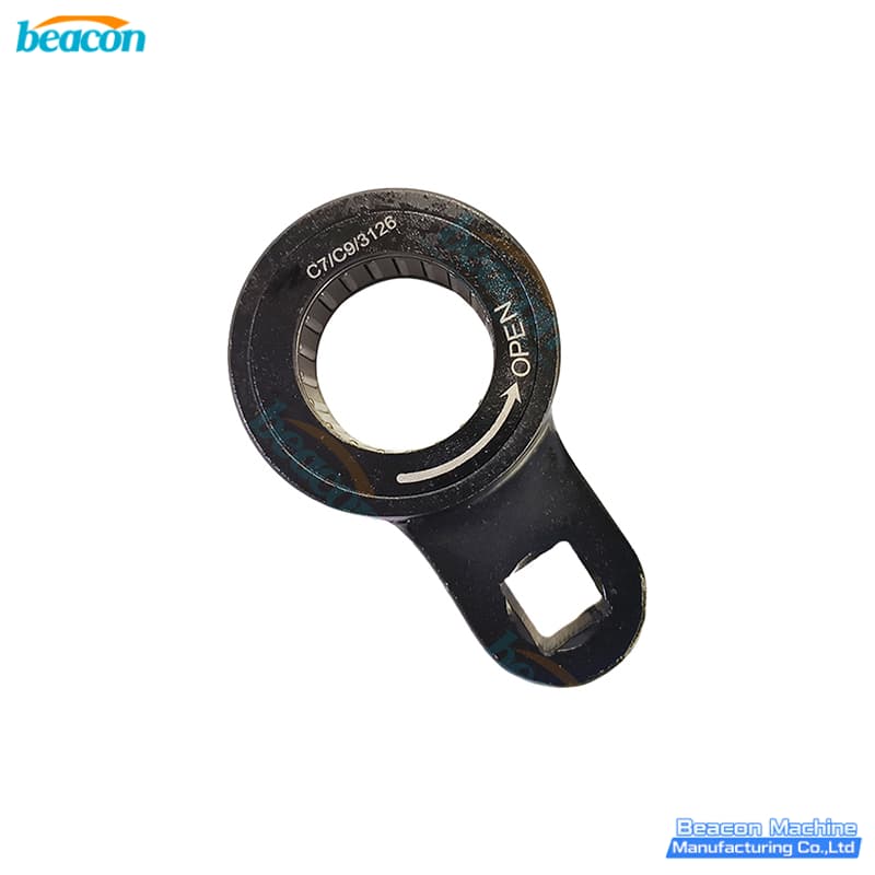
BEACON MACHINE G4-67 Professional Caterpillar C7 C9 3126 Injector Pressure Cap Wrench | HEUI Injector Disassembly Wrench
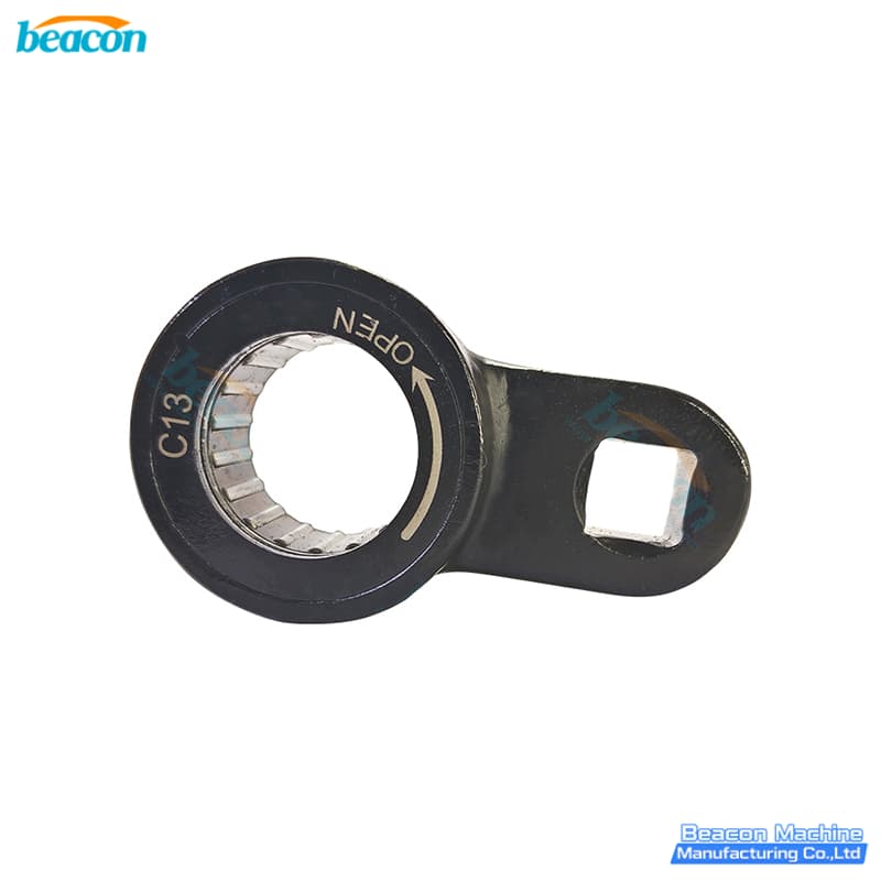
BEACON MACHINE G4-66 Professional Caterpillar C13 Injector Pressure Cap Quick Release Wrench | Heavy Duty Caterpillar Injector Service Tool
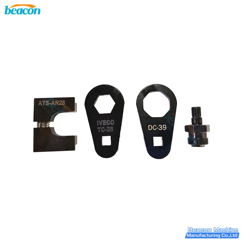
BEACON MACHINE G4-65 Professional Heavy Duty Iveco Diesel Injector Installation Tool Kit | Precision Injector Service Tool
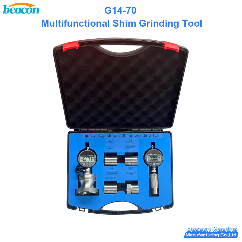
G14-70 High Precision Professional Common Rail Injector Shim Grinding Station | Injector Repair Tool BEACON MACHINE
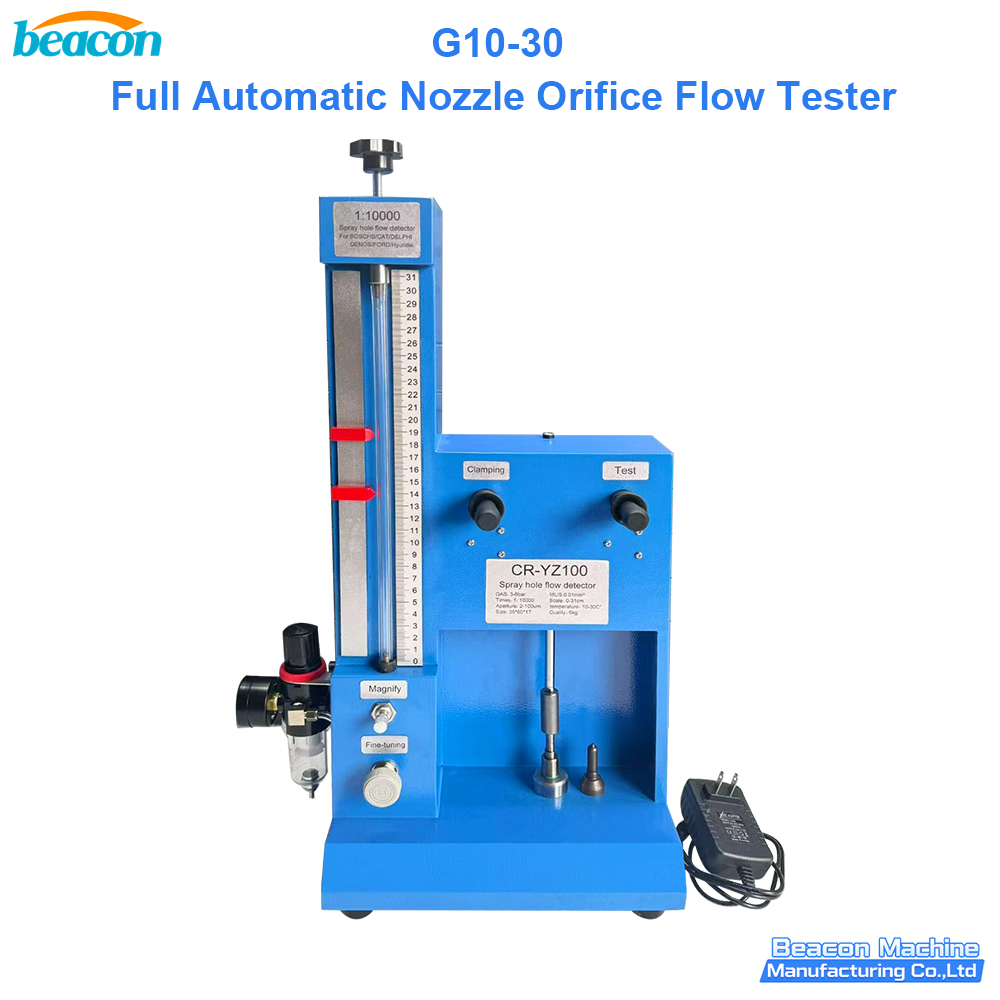
G10-30 High Precision Automatic Nozzle Orifice Flow Measurement Instrument | Professional Nozzle Orifice Flow Tester BEACON MACHINE
Related News
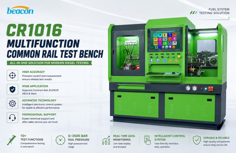
Enhancing Workshop Accuracy with the CR1016 Multi-function Common Rail Calibration Solution: The Ultimate Common Rail Test Bench and Diesel Injector Tester Guide
Jun. 12, 2026Upgrade your repair facility with the CR1016 multi-function common rail calibration solution, a premier common rail test bench and diesel injector tester. Optimize performance for Bosch, Denso, and Delphi fuel systems with precision automated diagnostic reporting today. (41 words)+ Details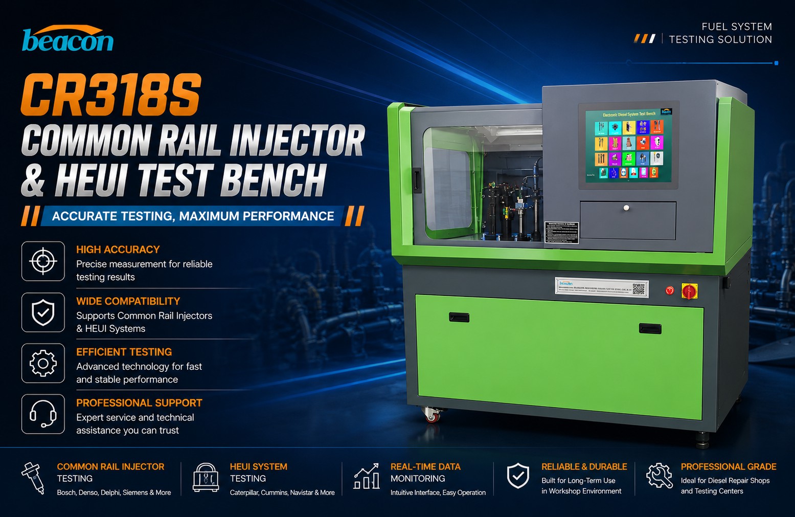
CR318S High-precision Diesel Injector Diagnostic Solution: Mastering the CR318S Common Rail Test Bench and HEUI Injector Tester BEACON MACHINE
Jun. 02, 2026Maximize your workshop ROI with our high-precision diesel injector diagnostic solution. The CR318S Common Rail Test Bench and HEUI Injector Tester offers 2600 Bar pressure and specialized Caterpillar C7/C9 testing for global engine service professionals.+ Details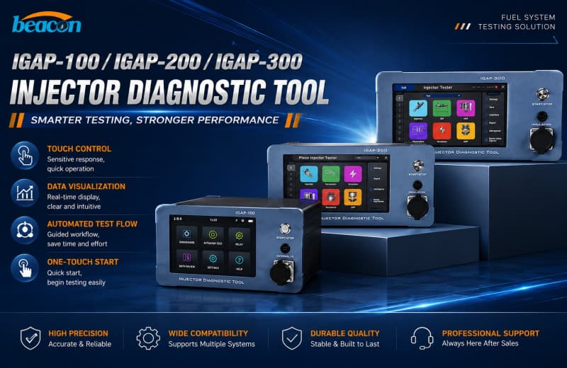
NEW Tester iGAP-300 Series: Choosing the Best Handheld Diesel Injector Diagnostic Solution for Your Common Rail Injector Tester and Piezo Injector Tester Needs-Beacon Machine
May. 29, 2026The IGAP-100 IGAP-200 IGAP-300 series offers the most advanced Common Rail Injector Tester and Piezo Injector Tester technology, featuring 7-inch HD touchscreens and automated reporting for global workshops.+ Details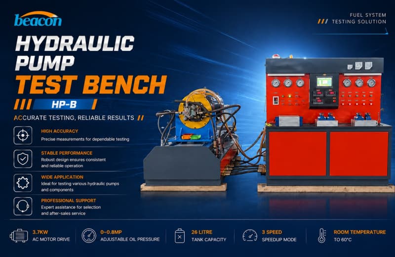
Heavy Duty Hydraulic Pump Calibration Station: Optimizing a High Pressure Hydraulic Pump Performance Testing Solution with the HP-B Hydraulic Pump Test Bench
May. 27, 2026Maximize industrial efficiency with our heavy duty hydraulic pump calibration station. Discover the high pressure hydraulic pump performance testing solution via the HP-B Hydraulic Pump Test Bench, featuring options up to 355KW and 700Bar for worldwide hydraulic service centers.+ Details
about beacon
PRODUCTS
contact us
TEL: 0086-13583836021
WhatsApp:+86-13583836021
Email: anneli@beacon-machine.com
Add: High Tech Industry Zone of East Tai an city,Shandong Province,China

WhatsApp

Wechat